Return
the Sharpening Techniques
The
Bench Sander Blade Grinder MK II
The
following article is a composite of posts written on the Ubeaut
woodwork forum from April
2005.
I have
replaced my Belt Sander Grinder with Mark II. This not only involves
a new jig, but also a new machine.
The original machine
developed electrical problems (in the on-off switch) and, after one
unsuccessful repair, I accepted Carba-tecs offer to return it (at
full refund) and upgrade the machine (my cost). Its replacement is
the Carba-tec SB-609,
a 6”x9” machine. Compared to its predecessor, it is
bigger and more powerful. Note that this is not necessary for the
purposes of grinding/sharpening blades, as the original machine was
satisfactorily specified in spite of being 1/3 hp and 4” wide.
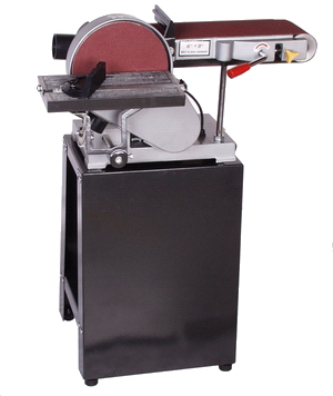
Carba-tec
described the SB-609 as follows: New model
features graphite slip pad and dust extraction outlet. Powerful 3/4
hp motor will not stall under pressure. Disc table tilts to 45
degrees. Belt platen swivels for horizontal or vertical sanding.
Quick-release lever makes for fast belt changing. Stand and mitre
guide included.
I needed to fit a jig
to the new machine and, although I could modify the old one to fit, I
thought that I'd make a new one – one that included all the
features I had previously described in the earlier article.
The
other area I was interested in sharing was my efforts in machining
metal, in this case aluminium, with the few related metal working
tools I own. If I can do it, then others can too!
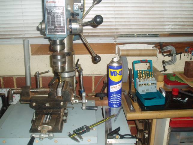
Below is a
picture of my Poor Man’s Metal Machining setup: drill press,
2-dimension vise, drill bits, cheap set of taps and dyes, squares,
scribe, digital caliper.
It
begins here …
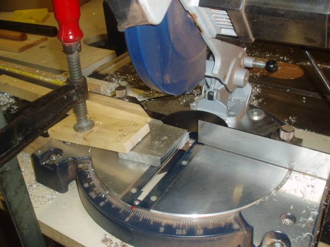
The first step
was to cut up a few pieces of aluminium. I did this on a Mitre Saw
(cheap GMC) …
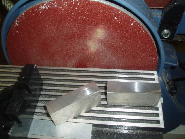
… then
ground them square on the belt sander …
The
plan for the jig was to modify the design by adding height
adjustability to the toolrest, a feature which many contributors have
believed important. I agree – height adjustability is not so
much a factor for setting the blade as it is for setting the tool
rest perfectly parallel to the table top. My earlier suggestion had
been to drill completely through the tool rest sideblocks, and to add
a height adjustment screw from underneath the block.
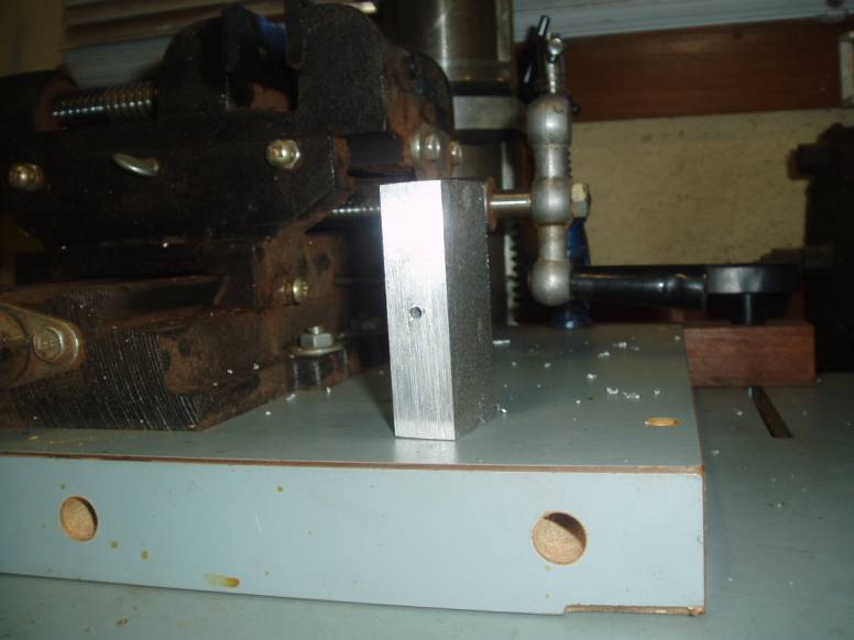
Drilling
the blocks accurately is made possible with a drill press and vise.
Make sure than you lubricate the drill bit otherwise it will overheat
and snap (don’t ask me how I know!). Below is a picture of the
underside of the drilled block, revealing that I got it right!
Height
adjustment screw: Drill a pilot hole all the way through the block.
Mine was 28 mm thick. Then drill from the underside 8 mm deep for a
thread you will later tap for an allen head bolt. From the other
(top) side drill a 20 mm deep hole for the toolrest legs (mine are
9.64 mm in diameter, so I used a 10 mm drill bit).
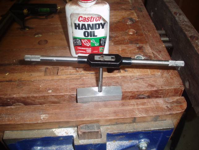
Tap the
height adjustment holes for the allen head bolt.
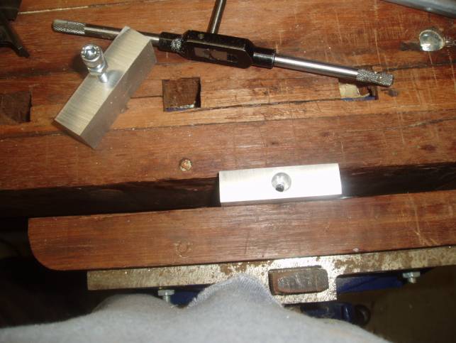
In
the next picture (below) you can see these holes more clearly.
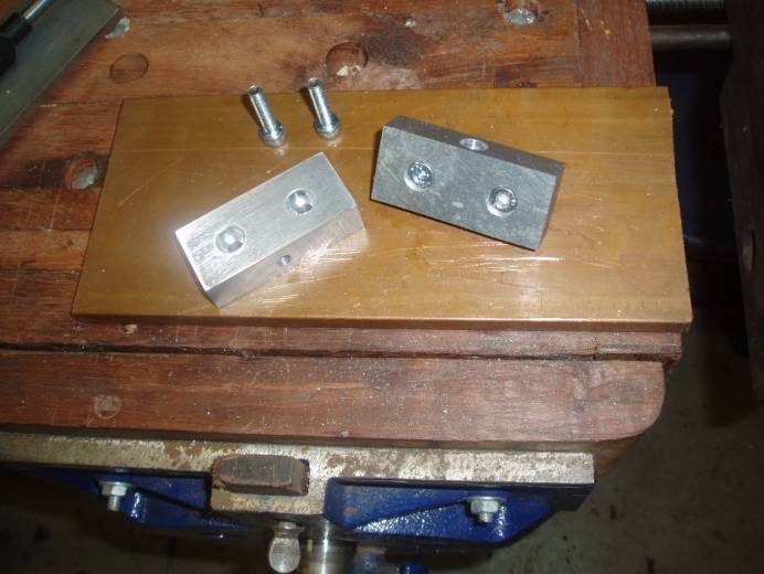
Finally,
drill the two holes that will fix the new toolrest block to the side
of the belt sander, and then drill to recess the bolts (also allen
head bolts). This completes the toolrest blocks. See picture below.
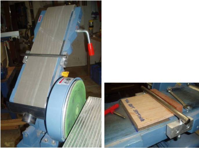
Here is
the pic of the final set up.
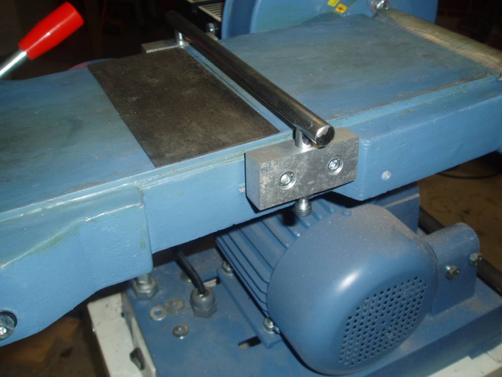
Note
that the belt sander table top was stripped of the graphite slip that
comes as standard equipment. This tends to be easily depressed when
pressure is placed in one spot. The underlying cast iron top was flat
and smooth. Nevertheless, to avoid any later problems with wear, I
contact glued a steel plate to the table. This was cut from an old
hand saw blade (cut with angle grinder, smoothed with files). (Edit:
this later proved unnecessary and was removed).
The
blocks were screwed onto the sides of the sander by drilling and
tapping holes. The set up process is the same as previously described
(in the first article). Care was taken to make sure that the toolrest
was square to the table top.
Steel washers were used as
spacers to center the jig.
The height of the tool rest was
set using a piece of 6mm MDF (reliable flat measurement) under it.
The height adjustment screws were locked in place with additional
nuts.
Instructions
for use
See the article on the MkI.
The
Honing Plate
This has also undergone a change. Where the MkI was
constructed out of two sanding disks epoxied face-to-face, now we
have chamois leather stretcher over and contact glued (use 3M) to the
face of the disk.
Start up the motor and cover the plate with
Veritas green rouge. Then freehand the bevel against this.
Place the blade down heel-first, and then rotate it until it is flat
on the plate. Just remember to hone with the turn. It only requires a
couple of seconds.
Regards
from Perth
Derek
April
2005