Back to Powered Tools and Machinery
Building a MFT: Part Two - making a rail hinge
In the
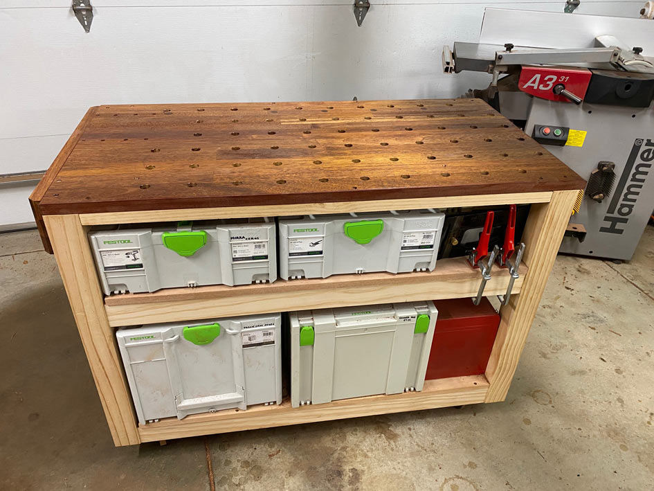
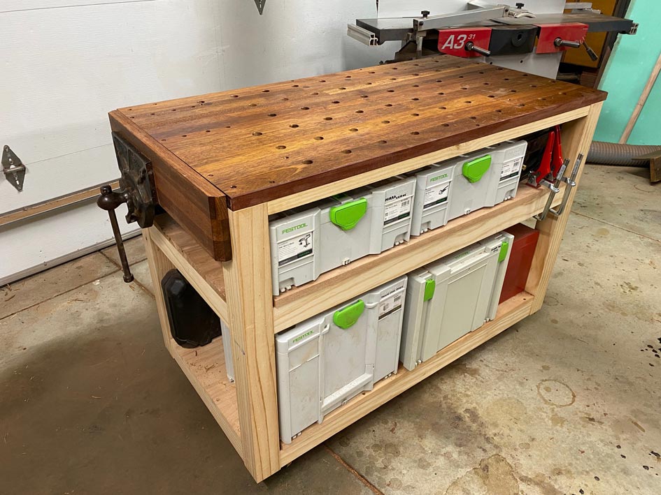
first segment of the MFT build, the aim was to construct a bench top
that would accept the Festool accessories for work holding. The MFT
would serve for routing, sanding, carving, and as an outfeed for a
jointer, slider and router table.
The 20mm holes were routed
using a CNC-made template.
It
needs to be understood that the reason for making the MFT was partly
due the cost of purchasing one in Australia being excessively
expensive (the Festool MFT sells for $1595), particularly so when I
am not sure how much use it will get.
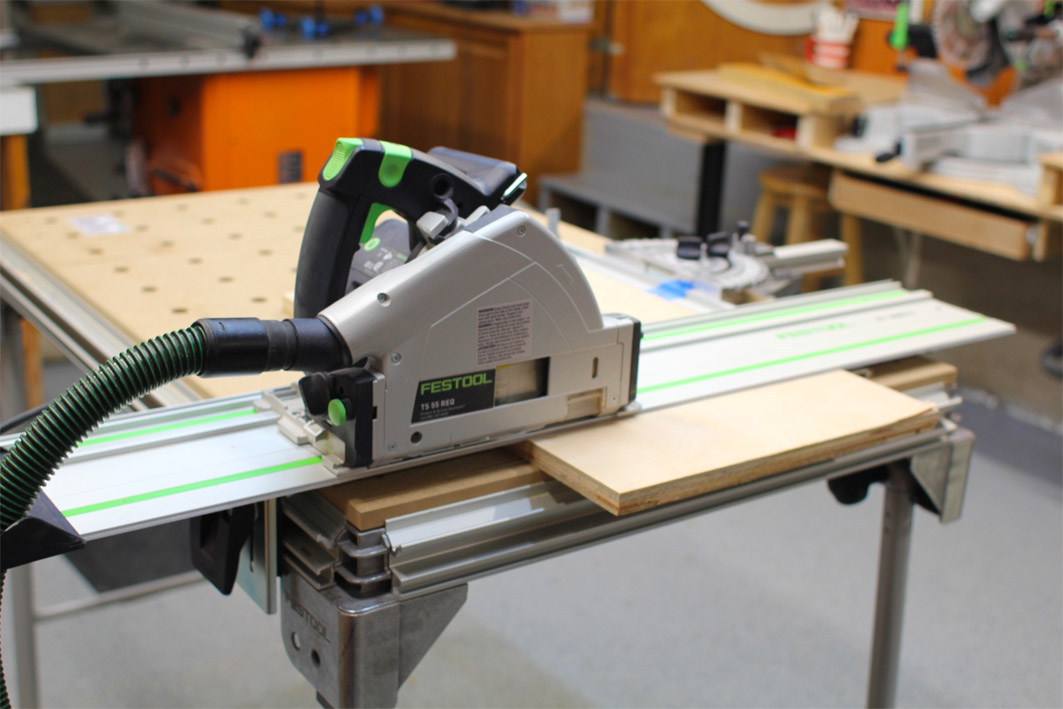
A large part of this
cost lies in the rail hinge and rail fence, since a typical use of a
MFT is for sawing ...
The
stability and ease of adjustment of Festool rail hinge has come in
for some criticism ...
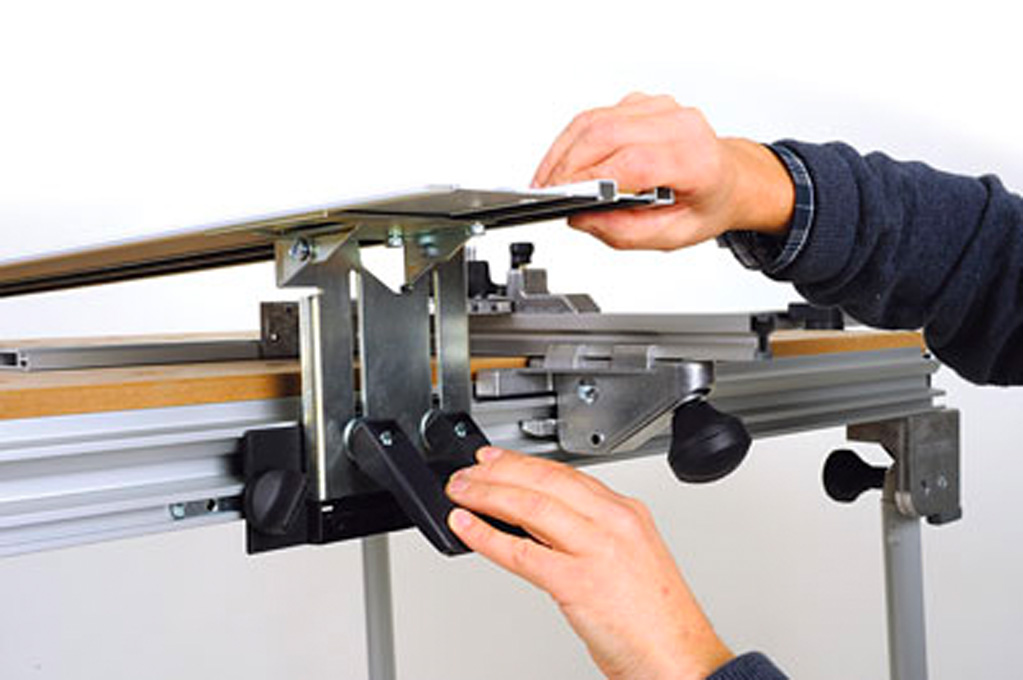
...
which has lead to aftermarket versions becoming available, such as
this Dashboard hinge ...
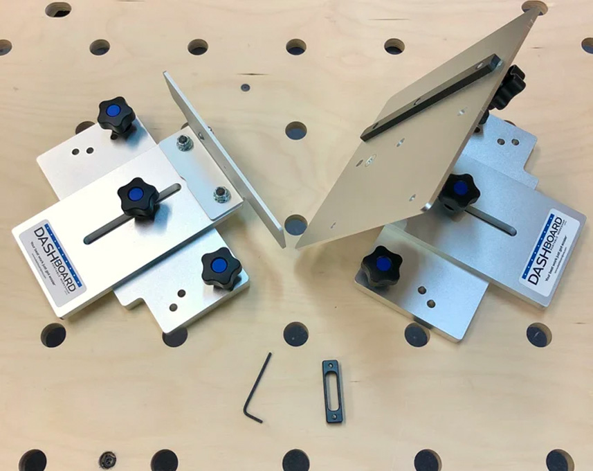
This
looks a beautiful piece of equipment, camera-level precise ... but it
would cost around $700 landed in Oz.
So I decided to build my
own. Two considerations - design and materials. The design is a mix
of ideas, some taken from other builds on the Internet, Peter
Millard's hinge design ..
.. and a few of my own.
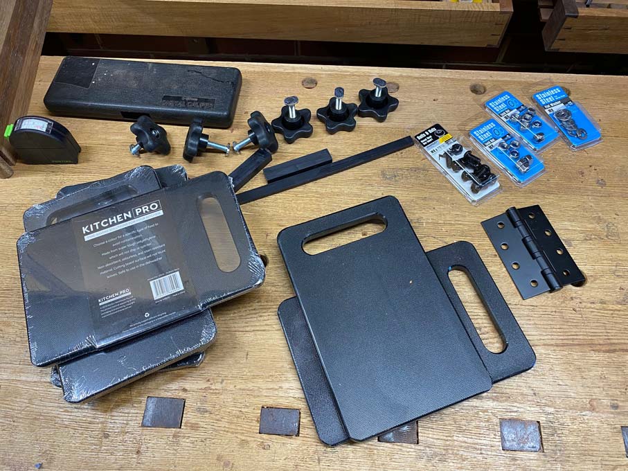
Fabricating in metal was not feasible as I do not have the tools to
work it. Using ply wood, MDF and even hardwood was rejected as these
are not durable enough. In the end I settled on nylon cutting boards
- cheap and very hard wearing.
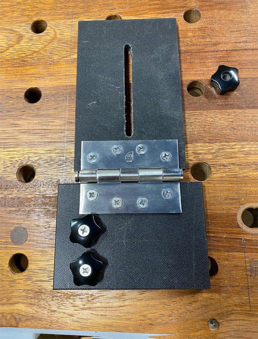
The
nylon cannot be glued, and so all bolt holes were tapped for threads,
and screwed together ...
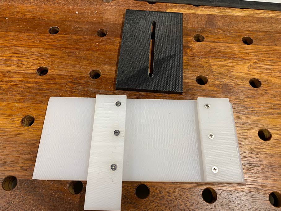
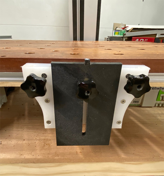
The
dimension across the top is 8" and the height is 5 1/2".
This
holder is used for both the hinge side (where the rail is connected)
and the pin side (where the rail is squared to the table) ...
Two
key factors are present: each part is built with care for precision -
errors are additive and will affect accuracy. Part of this is that
the hinge must not have any play.
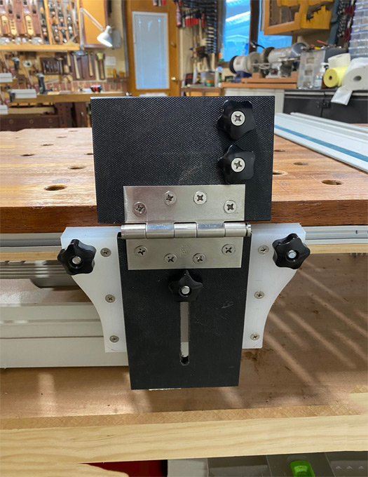
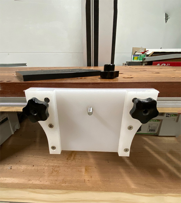
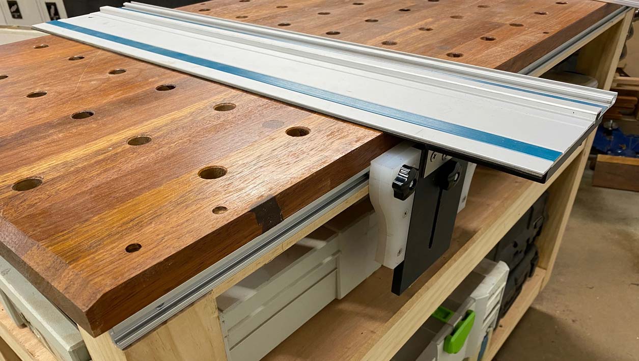
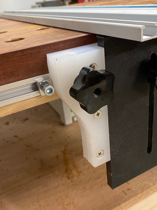
The
rail hinge is set at a height below the bench top when not in
use.
The two knobs (above right) tighten the connector to the
rail ...
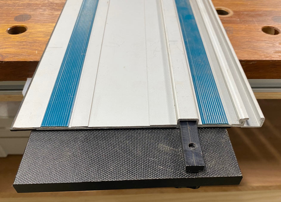
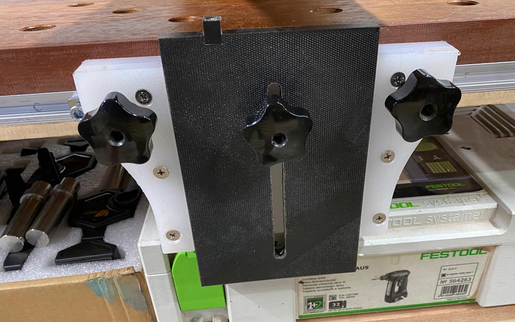
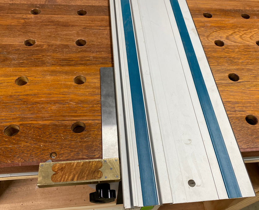
The
rail connector has rebates to fit the rail ...
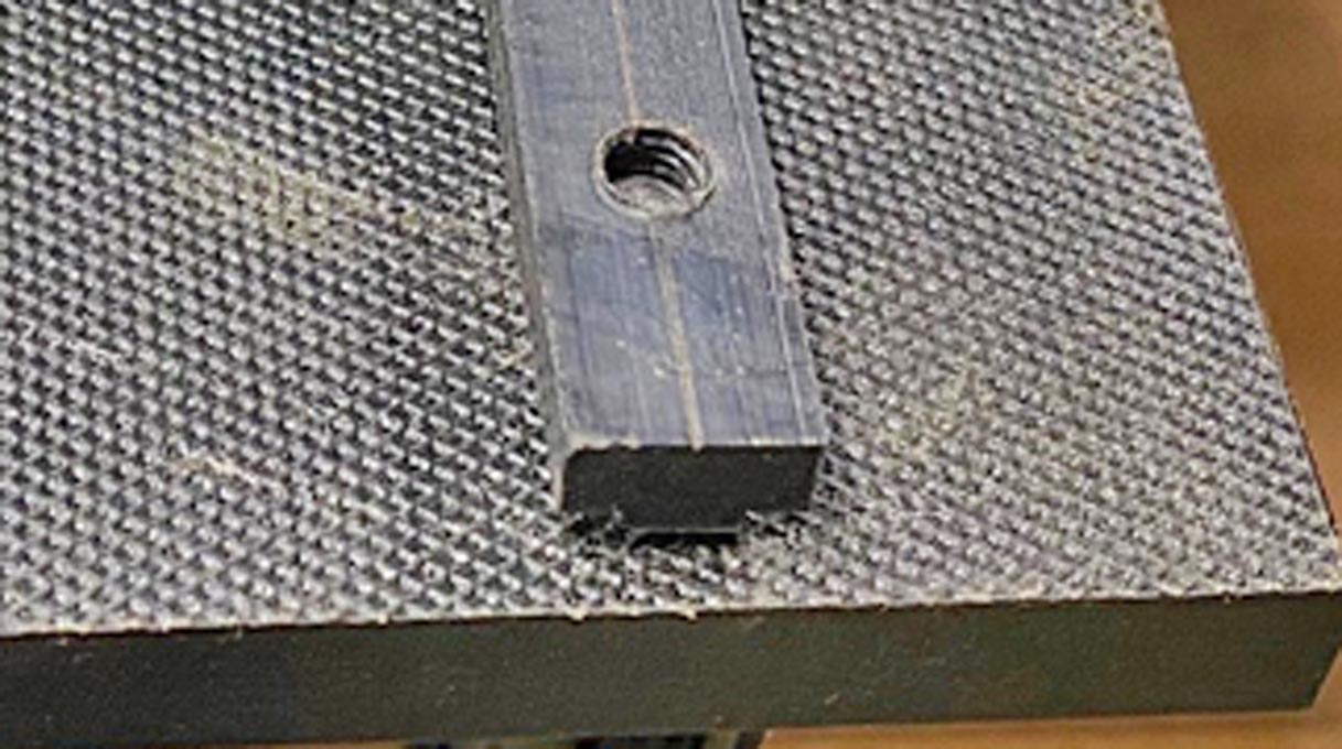
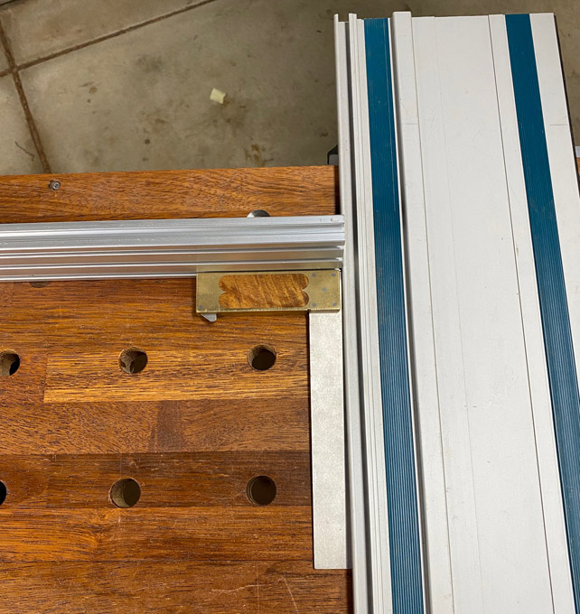
The
pin in the pin holder is square and sized for a tight slip fit ...
EDIT:
since building, the pin has been moved over to the left side of the
holder. This is to increase/maximise the support the rail receives.
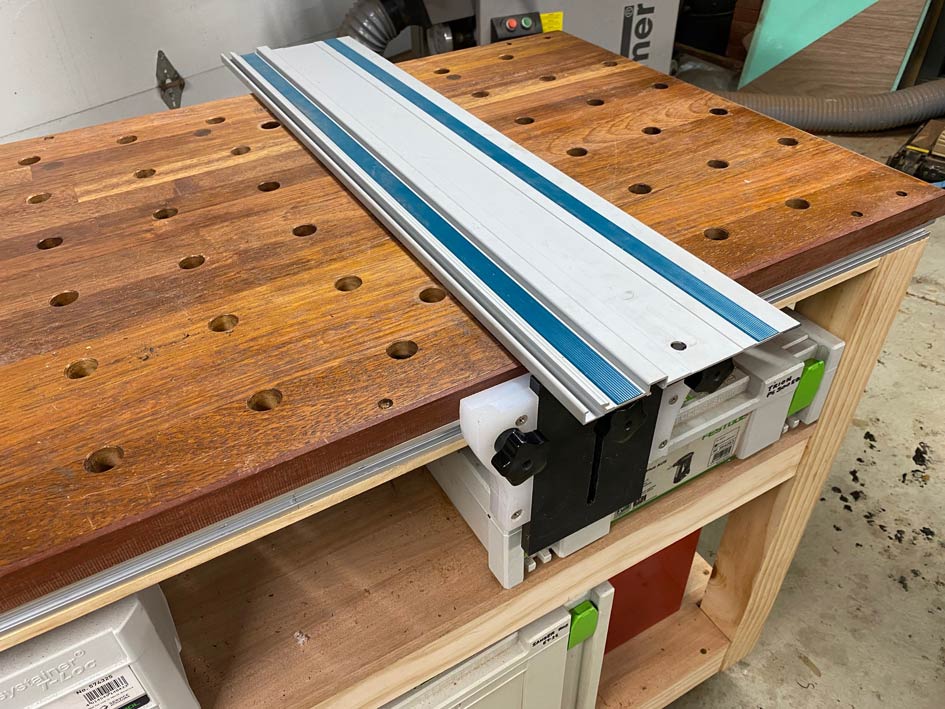
All
together - the rail swings over ....
...
and rests on the pin ...
The
rail is able to be lifted up out of the way in readiness to position
a board ..

All
feels rock solid.
Checks for square against a rear fence ...
...
and against the front of the bench (the ends are exactly parallel and
all the holes are square) ...
Lastly,
a stop is added to both hinge and pin holders, to allow exact
re-positioning ...
All
the best for the festive season.
Regards from Perth
Derek